

September 2023
How far is too far? – A simple solution to an avoidable phenomenon?
Emily Wainwright Chief Cardiac Physiologist, Diagnostic Cardiology, West Suffolk Hospital, UK
Disclosure: The author has no conflict of interests to declare.
Background
A remote monitoring transmission was received for ‘SVT’ and ‘non sustained’ episodes. Patient history revealed that the patient had a right sided dual-chamber Boston Scientific Essentio device which was implanted in Sept 2020 at routine boxchange. The original implant indication was 2nd degree AV block and intermittent CHB. Existing St Jude Medical atrial and ventricular lead (apical) remained in situ unaltered since original implant in 2008.
On review of the remote download, the presenting EGM demonstrated atrial flutter with ventricular pacing at AMS fallback rate of 60ppm. The patient was known to have paroxysmal atrial flutter and was anticoagulated. The patient was contacted and they reported ‘fleeting’ dizzy spells in recent days but no syncope. The ‘SVT’ and ‘non sustained’ episode EGMs all demonstrated a consistent pattern, an example of which is shown in figure 1 below.
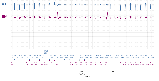
Figure 1: EGM for ‘SVT’ episode lasting for 34secs.
Automatic trend measurements from the remote transmission are shown below:
Atrium
• 2% paced
• Variable P wave 0.5 – 4.0mV
• Stable impedance ~460ohms
• No threshold measured (Aflutter)
Ventricle
• 88% paced
• Variable R waves 2.0 – 20.0mV
• Stable impedance ~480ohms
• High (chronic) but stable threshold 1.4V @ 1.0ms
QUESTION
What rhythm is demonstrated on the EGM?
Answer
Atrial Flutter with far field atrial oversensing
The EGM demonstrates Atrial Flutter with far field atrial oversensing (FFAOS) and subsequent ventricular pacing (Vp) inhibition. The longest period of Vp inhibition seen on available EGMs was 8 seconds, during which a ventricular escape rhythm at ~25bpm was observed (as seen in figure 1). There had been no evidence of this finding on episode EGMs from previous pacing checks.
Investigation
The patient was asked to attend clinic the same afternoon for further investigation. A chest x-ray was performed (Fig. 2) which did not show any evidence to suggest lead fracture, insulation breach or lead displacement. An echo demonstrated no significant change from previous scans – normal LV function, normal functioning aortic valve replacement and significant bi-atrial dilatation.
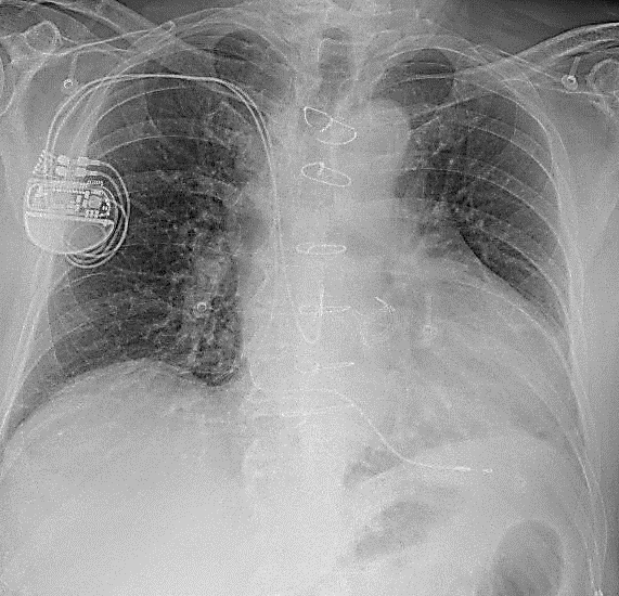
Figure 2: CXR demonstrating unchanged atrial and ventricular lead placement.
Explanation
The device is programmed DDD 50 – 130/min with bipolar atrial and ventricular sensing on Automatic Gain Control (AGC) at 0.25mV in the atrium and 0.6mV in the ventricle. The pacemaker lead trends showed high variability of R wave amplitude, ranging from 2.0 – 20.0mV, as shown in figure 3. In view of the low programmed ventricular sensitivity of 0.6mV with AGC, it is likely that the lower amplitude measurements are FFAOS signals rather than true R waves.
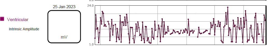
Figure 3: Variable ventricular intrinsic amplitude trend over 6 month period.
While we see far field R wave (FFRW) oversensing more often, FFAOS is uncommon, which is reassuring given that resulting ventricular pacing inhibition could be life-threatening for a patient with no underlying rhythm! There are few published cases on this phenomenon, but the association of FFAOS with a preceding reduction in ventricular sensitivity (Barold et al., 2002) makes the occurrence easier to understand from a programming perspective. This was evident in our case, where sensitivity was previously fixed at 2.0mV prior to boxchange and subsequently programmed to AGC 0.6mV on the new device. The issue was resolved in clinic by changing programming to fixed ventricular sensitivity of 2.5mV.
It is more difficult to understand how sensing of atrial signals on an apical RV lead can occur at all, simply due to the vast distance between the RV lead tip and the atria. Suggestions have been made in research by Martow et al. (2021) and in educational material from Ellenbogen (2020), including RV lead displacement to the AV junction / RVOT, defective insulation on the RV lead in the atrial region, presence of large muscular right atrial appendage, and atrial lead-RV lead interaction during systole. While we can exclude RV lead displacement in this case based on the chest x-ray, there was no definitive evidence which alluded to any of the other possible causes. However, normal device function has resumed with programming changes and the patient has remained symptom-free since then.
Learning points
-
- Be aware of nominal sensitivity settings, particularly when changing manufacturer / model at generator replacement.
- Consider making device less sensitive in pacemaker-dependent patients as highly sensitive programming is of low clinical utility in these patients.
- While useful in ICD programming, consider whether auto-sensitivity programming is necessary for your pacemaker patients.
References
P wave oversensing – Cardiocases (2020) Ellenbogen K. P-wave oversensing | Cardiocases
Martow et al. (2021) Sense and Sensitivity: P wave oversensing causing inhibition in a dual chamber pacemaker and practical considerations. Heart Rhythm Society Case Reports: Volume 7, Issue 8, P546-548. Sense and sensitivity: P-wave oversensing causing inhibition in a dual-chamber pacemaker and practical considerations – HeartRhythm Case Reports
Barold et al. (2002) Far-field P-wave sensing by the right ventricular lead of conventional dual chamber pacemakers. J Interv Card Electrophysiol. 2002; 6: 77-80.
Disclaimer: The British Heart Rhythm Society (BHRS) collates submissions for the ECG/EGM challenge on this website. These submissions, along with any accompanying answers, are provided by external contributors and are published for informational purposes only. BHRS does not endorse, guarantee, or warrant the accuracy, completeness, or reliability of any submissions or answers provided.